
1/12 Porsche 917
ABC-Brianza Resin Kit
Build Report by Mike Kendel
Part 1
Work commenced on this kit several months ago, but was slowed due to a number of factors, including among others, health issues and gaining familiarity with new machinery and processes. To date the progress is shown below in the following areas:
Wheels and Tires
The kit wheels were rudimentary. There were no inner rims and, in the case of the rear tires, the aluminum turned rim ended approximately ¼” inside the tire center so there was not even the illusion of an inner rim. In addition the wheel centers were somewhat rudimentary and included axle holes which were neither centered nor the right size for even the basic axle rods included in the kit.
The actual wheel center of the spare tire was a far better wheel center than the ones for the road wheels but it suffered from inaccurate centering and size of the central hub. A new center section was turned and installed. Rubber molds were then made from this modified part and from these came the centers used in the main wheels.
In addition, the original spare tire suffered from irregularly spaced and cut “tread” grooves so these were filled and re-cut on a lathe. As this piece is mounted with the inside of the wheel upwards in the car and the original had no internal wheel half in the inner portion, a new wheel inner half was turned and installed so that the part would look proper when installed. In addition a raised lip was added to the outer rim per prototype photos.
For the main wheels, inner wheel halves were machined for all wheels and new center sections were cast from the modified spare tire centers. The finished Rear and Spare tires below reflect the completed assemblies with only the addition of air valves and weathering remaining. These will be done as part of the final assembly.


Tires treads were sanded to minimize flash and give worn look. Depth of tread limited amount of sanding here so some flash / un-evenness remains. Tires were then clear-coated, decaled, and dull-coated on outer side only. Wheel mounting centers will be weathered to reflect repeated mounting, un-mounting but will otherwise not be heavily weathered.


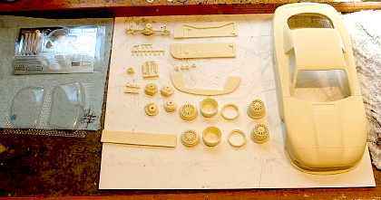
Comparison of stock kit parts (right) and modified / new parts (left). New inner wheel turning is at lower left and new center wheel casting is in lower center. Note comparison between new wheel center and original wheel center.
Engine Block
The engine block is being built up of styrene. Earlier report showed basic block shape as seen in mill below. Newest addition are mounting bosses, oil passages, cam drive tower mounts, and fan drive tower. These large bosses are assumed to be for boring plates since these bosses are not used on the complete engine.
 Early machining on blank of new block.
 New Engine Block in front of kit engine.
(New block shows correct scale length of engine. Original engine does not match length in scaled drawings.)

Starter
The kit did not have a starter and it is visible when the engine compartment is open. So a starter was assembled using resin castings of a starter out of a 1:12 scale Tamiya Porsche 935 kit. This starter needed to be heavily modified to match prototype photos.

Tamiya starter on right is simplified and has incorrect mounting configuration. These were corrected on new starter on left.
This same procedure will be used for other parts, such as the alternator and possible the oil filter housing, both of which are highly visible at the front of the engine but neither of which is included in the kit.
Comparison between many kit parts and scaled photos and drawings shows numerous incongruities. The basic wheel base is off by about 6” scale inches. The Body shows compression in the cockpit area through the window/door area of approximately 3 scale inches and also a similar amount in the nose. The front floor pan and side pods need to be extended also.
The kit was supplied without a fuel injection pump and a parts order to Brianza did not rectify this even though the part was ordered. This part as well as virtually the entire intake tract and exhaust system will need to be fabricated from scratch. This adds complication to the fabrication of the engine. In addition the transmission does not match scale dimensions and contains several highly visible inaccuracies, so it will need to be heavily modified.
The kit has no suspension or steering components and contains only two rudimentary axle rods. In addition, the “frame” components supplied in soft white metal are inaccurate and incomplete. This means that in addition a full suspension component set and frame will need to be fabricated as well as brake components. To this end, a surface plate type mount fixture is being generated to use as a build fixture.
The kit is proving to be a challenge but the positive side of all of this is that the model should be an exciting representation of a very significant and charismatic racing car.
Progress since the last report is as follows:
Wheels and Tires
All tires and wheels, including the space-saver spare have been painted decaled and assembled. These are now ready to be attached to the model during final assembly.
This final work on these included machining the inner flanges for the drive pins in the hubs and assembling them into the wheels.
Engine Block / Transmission
Due to need to speed up progress with the model, it was decided to abandon the scratch built motor and proceed with the kit piece. This involves some compromises, because the cylinder spacing on the model engine is too close and results in the engine being too short.
In addition, all surfaces on the model parts are very roughly finished with non-parallelism and casting flash. So all surfaces received a preliminary sanding process to get them approximately true and flush.


These pictures show the rough condition of the engine block casting. Note the presence of casting flash and filled location holes. Because parts were only roughly finished, many surfaces are not planar and not aligned.
Once the parts had been cleaned of flash and sanded roughly to shape, the problem of aligning the parts to one another had to be faced as there are no alignment features. To solve this problem, all of the major parts needed to be “keyed” to one another. This was accomplished by making several measurements, (and some assumptions), and then drilling holes for 1/8” pegs at strategic locations as shown below…

This allowed rough assembly of the power-train components to see how things lined up…


This in turn allowed some checks to be made against the blueprints. Among other things, this shows that the transmission needs to be extended from the engine by at least another 1/8”, as shown below.

This is actually handy because the transmission shape currently bears little resemblance to the actual transmission in the car and the additional clearance will allow the front to be reshaped to include the transmission “ears” that mount to the chassis.
Body / Chassis
The bottom casting for the chassis was originally mis-cast by the factory to be approximately twice the thickness that it should be (in addition to having some very weird edge formations!) This meant that it stuck out below the body proper as shown by the edges highlighted in black below.

This was corrected by some careful sanding, but that revealed another problem. The floor pan is too short to match up correctly with the body.

The left side of the photo shows proper alignment of the rear fenders, and this translates to the firewall at the back of the cockpit being in the right place. With this basis, it is apparent that the front end of the floor pan is misaligned by roughly 1/8” as evidenced by the gaps visible at the right side, ahead of the front wheel wells. This situation will be corrected by cutting and “stretching” the floor pan, which will actually go some distance towards correcting the wheelbase discrepancy in the model. This will be undertaken in the next part’s tasks.
Cockpit Electrical Details
The kit contains none of the electrical equipment or wiring details that provide a large part of the visual interest of the cockpit, (to say nothing of historical accuracy!) To this end the battery, battery tray and hold downs, ignition modules, and two front coils must be fabricated along with any circuitry and most of the instrumentation and warning lights.
To that end research was done to find the most likely type and size of battery to model and a Varley Type 30 was selected. The four Capacitive Discharge Ignition Modules must also be modeled and they are shown semi-complete, along with the battery in the picture below. All of these parts are constructed from styrene plastic shapes.

Assorted Notes
Research continues on various aspects of the car. In addition to the battery dimensions, more information relating to the switches, warning lamps, and instrumentation has been found and will be incorporated into the seats. A lot of searching in old literature and on the internet is also slowly turning up more details on the appearance of the 4-speed gearbox that is simulated in this kit, so that will be incorporated in the rebuild of that part.
For the next month, work will continue on rough shaping of the engine and gearbox, as well as stretching the floor pan, (and possibly the body to correct all of the wheel base discrepancy. In addition interior parts will continue to be made and completed.
Progress since the last report is as follows:
Birth of FrankenPorsche
Given the major discrepancies between the body dimensions and the scale measurements, or even more basically, the discrepancies between the kit body and floor-pan, the decision was made to make the body more closely match the dimensions of the prototype. And then to modify the floor-pan to match the corrected body dimensions.
For the main body, a detailed comparison of the plan dimensions with the dimensions of the actual body casting showed that two cuts could form the basis of “stretching” the body to match the scaled major dimensions of the real car. The cut lines are shown as tape lines below:

Unfortunately, this kind of cosmetic surgery needed to be both structural and precise in its results. Because of this, it wasn’t possible to just start hacking on the body and expect a good outcome. In order to maintain the alignment of the parts in the long axis of the car and keep them all on the same level, a series of holes were drilled into the body from the front. These holes would be filled with plastic rods which would maintain the critical alignment of the pieces.
The first two holes were drilled into the middle of the smaller driving lights in the front section of the car. (The holes for the rods in the middle two pieces would have been too deep to drill with the nose on anyway).
Once the first two holes were in place, the first cut could be made across the body and through the headlight recesses. Once the front piece was separated, the holes could be drilled for the middle and aft section and then that cut could be made.
The next two pictures show the body sections after cutting and with the plastic rods inserted for alignment purposes.

This picture was taken before the parts were re-joined. The plastic alignment rods are clearly shown.
The part of this cut that goes through the fender is at approximately the front axle center line. It will result in wider wheel wells as viewed from the side of the car, (which agrees with reference data), and will also allow the wheel base of the model to stretch the extra ¼” it needs to make it correct.

When it came time to start rejoining the pieces, the parts were carefully aligned and super-glue was used to tack them all in place. Once this was done, crude tape dams were made and a core of epoxy glue was poured in to create structural strength.
Following the epoxy, casting resin similar to the orginal body material was used to fill the remaining space. In the initial pours of resin, clay was used to form the dams and “molds” for the resin. The remains of the blue clay are also visible here.
Any process like this is iterative, meaning that it takes several passes to make everything right and there is a sculptural element to it. If the body was just cut and then bridged, the lines would not end up right, so there is an element of building up material only to sand off most of it. However, at this point, no soft putty is being used because the model needs a solid structural basis.
At this point also, it is time to deal with the “bubbles” that are a result of air trapped in the mold when the original casting was poured. All resin models have these to a greater or lesser extent, but I have to say that these are about the worst I have seen in my limited experience.
All of these holes are filled with casting resin also to try and minimize the material differences. This will hopefully minimize issues with the paint later. The upper surfaces are now mostly built up, and again casting resin is the primary top surface for the reason given above.
Below is a picture of the current state of the body. Most of the profiles have been rebuilt and the rough body shaping is done.

And now, to the Chassis
Now that the body is altered, it’s time to get the chassis/floor-pan set for alterations also. Remember, it needed to be altered anyway since it didn’t line up with the body correctly even before the body was altered. As this operation entails having to remove a lot of the molded in “frame rails,” many of these molded features will be replaced with brass tubing both to lend strength to the front structure and also to provide a base to tie in the chassis which will have to be built from scratch from the firewall back.
Here’s a picture of the chassis in the mill and cutting has already commenced…

Last and least…
The only other component to receive attention this month was the driver’s seat. Basically it was cleaned up and the blemishes were filled. It was also carved to represent the glassed-in reinforcement in the lumbar area that most of the reference photos show in the race cars. The earliest seats did not appear to be reinforced, but apparently strength issues led to these modifications. They look like glassed-in foam shapes and probably serve to help with the seat stiffness.
The picture at left below is the stock casting, and the cleaned up version is at right.


The basic seat still needs the mounts for the seat itself and the seatbelts fabricated and attached. In addition, it will receive a texturing to simulate the glass matt that the originals were made from and… upholstery! The seat will be covered in a red material that simulates cloth and a seat belt set will be fabricated.
Well that’s about it for Part 1. In Part 2, the body work will continue, as well as the interior framing and initial build up of the passenger compartment.
Stay tuned…